Half Cell corrosion mapping is an effective method for assessing the severity of corrosion activity in concrete structures. It is the most well-known procedure to identify the likelihood of active corrosion; however, the test does not provide any information about the kinetics of corrosion activity. The easy and cost-effective procedure of the test makes it popular among engineers and structure inspectors. The method has been used for bridge deck inspection, parking garages, corrosion monitoring of reinforced concrete beams, girders, and piers.
What is Half Cell Corrosion Mapping
Half Cell corrosion mapping consists of measuring the potential difference between a standard reference electrode, normally a copper/ copper sulfate (standard portable half-cell) placed on the surface of the concrete with the steel reinforcement underneath.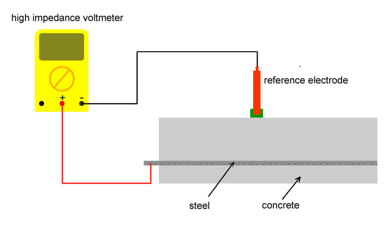 Half Cell corrosion mapping offers a rapid, cost-effective and non-destructive way for corrosion assessment. The test provides valuable information on the likelihood of corrosion, and helps in the quality assurance of concrete repair and rehabilitation. Several standard associations have standardized the test procedure including the ASTM C 876, UNI 10174 and RILEM TC 154. Depending on the measured half cell corrosion potential value, the probability of active corrosion is determined.
When the half cell potential measurement is more negative than -350 mV (CSE electrode), then the chance of having active corrosion is more than 90%. When the measured value is more positive than -200 mV, the chance of active corrosion is less than 10%. For potential values between -200 mV and -350 mV, there is uncertainty in interpreting the test results.
How to Perform Half Cell Corrosion Mapping
In ideal laboratory condition, performing half cell corrosion measurement is straight forward; however, performing the test in the field can become challenging. The following steps will help you perform an effective and reliable measurement in the field:
1- Measurement Points
The first things first is to know the test locations. In general, a schematic grid will help you with smoothly taking the measurements, and managing test results. There is no general rule about the grid spacing. A finer mesh will be more precise, but also more expensive. Wide spacing can reduce the resolution of test results, and may result in inaccurate half cell potential measurements. A suitable spacing should be selected with regards to the area under investigation.
2- Rebar Connection / Connectivity Test
Half cell potentials at each test point is measured to an identical reference point. An electrical connection to the rebar network is required at this reference location. normally, concrete cover should be locally removed (this can be achieved by drilling into concrete), to establish a sound electrical connection to rebar. To do so, one needs to locate the rebar first (this can be done by using a rebar locator). Rebar network normally provides a connected mesh. However, in larger area, such as deck slabs, one needs to check if the steel rebar network is connected.
3- Electrical Connection to Voltmeter
The connecting lead cable from the negative terminal should be connected to the reference electrode, while the other lead wire should be connected to the rebar network at the reference location. The voltmeter should be able to measure direct current (dc) voltage, and have the capacity to be battery operated. The voltmeter should have a variable input impedance ranging from 10 to 200 MΩ may be used to determine the input impedance required to obtain precision readings.
4- Pre-wetting the surface
If the surface of concrete is too dry, the pre-wetting is required. Pre-wetting can either be achieved by spraying the water over the location to be tested, or through using a wet sponge. ASTM C 876 describes how suitable pre-wetting condition can be achieved.

5- Perform Measurements
At each location, the value of half cell potential should be recorded to the nearest 0.01 V (ASTM C 876). For each point, record the coordinates of the test point, as well as the corrosion potential value. If the weather condition, including the temperature has changes, the values of the half-cell measurement should be adjusted for temperature variations.
How to Present Half Cell Potential Measurements
Half Cell potential maps are widely used to present the test results. The contour maps can show the gradient of the half cell potential values, can easily be interpreted. An example of this contour maps is illustrated in the figure below. Alternatively, results can be presented using cumulative frequency distribution.
Half Cell Potential Measurements – Influencing Parameters
When it comes to half-cell potential values, one should take into account the effect of environmental conditions (such as moisture and humidity), as well as the properties of concrete materials (dense concrete versus porous concrete, carbonated concrete). According to Ping Gu and J.J. Beaudoin (1998) The following parameters can influence the corrosion potential measurements:

+ Electrical resistivity of concrete
+ Density of concrete
+ Cover thickness
+ Epoxy coatings
+ Presence of Asphalt overlays
+ Oxygen Availability
Remarks on Half Cell Potential Test
+ Obtaining effective and reliable half cell potential measurement is difficult when the electrical resistivity of concrete cover is high. Wetting concrete surface can help reduce the impact of electrical resistivity on half cell measurements. Dense cover, as well as thick concrete cover may reduce the amount of oxygen, and results in more negative half cell potential values, without necessarily having active corrosion.
+ Decrease in the oxygen concentration at the surface of the steel reinforcement in fully saturated concrete will result in a more negative corrosion potential readings.
+ Another challenge is when the concrete surface is covered with coatings, or asphalt. Effective measurements is not possible over asphalt overlays. In this case, the general practice is to drill into the asphalt layer, to get to the surface of concrete. conductive solutions can be used to make electrical connections between the electrode and the concrete surface.
+ When doing a half-cell potential test, one should remember that the surface should be free of paint, and chemical epoxy coatings. Also, the test on stainless steel reinforcement and epoxy coated rebar will increase the chance of error in making the measurements.


4 Methods of Condition Survey for Bridge Decks | FPrimeC Solutions
[…] the use of ground penetrating radar (GPR), impact echo (IE), ultrasonic surface waves (USW), half-cell potential (HCP), electrical resistivity (ER), and chain drag/hammer sounding for bridge deck […]
Corrosion Monitoring of Reinforced Concrete Structures | FPrimeC Solutions
[…] Learn more→ HALF-CELL CORROSION POTENTIAL MAPPING […]
What NOT TO EXPECT from Pile Integrity Testing? | iPile
[…] Integrity Test does not provide any information about corrosion activity in concrete. Unlike half-cell potential measurement, or the corrosion rate measurement techniques, the PIT method cannot be used to study the […]
How to Evaluate Bridge Abutments? | FPrimeC Solutions
[…] Corrosion mapping is a widely used test procedure to identify the areas with active corrosion activity. The test can reveal the locations with high likelihood of corrosion; it can also be used to evaluate the quality of repair. Engineers should consider that any coating or paint residue should be removed before conducting the test. Read More: Half-Cell Corrosion Mapping […]
Carlos Aliaga
Wonderful article as usual folks!
Kostas
Great advice, thank you very much!
Non-Destructive Testing for Detailed Bridge Condition Survey | FPrimeC Solutions
[…] such as the ground penetrating radar (GPR), impact echo (IE), ultrasonic surface waves (USW), half-cell potential (HCP), electrical resistivity (ER), and chain drag/hammer sounding for bridge deck […]
NDT Methods for Concrete Imaging and Scanning | FPrimeC Solutions Inc.
[…] Half-Cell Corrosion Potential Mapping - Identify locations with higher likelihood of corrosion […]
Non-Destructive Testing for Structural Condition Assessment | FPrimeC Solutions Inc.
[…] Half-Cell Corrosion Potential mapping is a quick non-destructive method for evaluating the likelihood of corrosion in concrete structures. It can be used to assess the probability of having active corrosion. The simplicity of the test makes it popular for inspection of large areas, such as parking garage slabs, and bridge decks. The test can also be used to verify the quality of a repaired concrete structure. […]
PCTE
Proper explanation is given. Great writing. keep it up!
Non-destructive Evaluation of Concrete in Mine Facilities - FPrimeC Solutions Inc.
[…] The Half-Cell Corrosion Potential test can help identify the likelihood of corrosion in RC components. This is very useful to assess the condition of an existing asset, plan for effective repair, and evaluating the quality of a previous repair job. […]