In this article, we will briefly present and discuss Impact-Echo (IE) method for testing concrete structures. The method has proven to be extremely useful in evaluating the thickness of concrete elements from one side (e.g. tunnel lining, culvert wall, bridge abutment), determining the depth and location of subsurface defects (e.g. cracks, voids, honeycombing, debonding) within concrete, and estimating the depth of surface-opening cracks. The test method was first adapted in 1998 as a standard test procedure by the American Society of Testing Materials (ASTM C 1383) “Standard Test Method for Measuring the P-Wave Speed and the Thickness of Concrete Plates Using the Impact-Echo Method.”

Impact Echo 

Impact Echo is a non-destructive testing (NDT) method for structural integrity testing of concrete and masonry structures. This method was first developed to locate flaws and voids in plate-like concrete structures (such as bridge decks, retaining walls, and slabs). Impact-echo test basically works based on the generation of stress waves through a short-duration mechanical impact on the surface of concrete element. Followed by the mechanical impact, reflection and refraction of stress waves from internal interfaces (concrete-crack, concrete-air, concrete-rebar) or external boundaries (echo) is recorded through a proper transducer (e.g. piezoelectric accelerometer or geophone). The reflectogram is analyzed in either time-domain or frequency-domain.

The test method was first adapted in 1998 as a standard test procedure by the American Society of Testing Materials (ASTM C 1383) “Standard Test Method for Measuring the P-Wave Speed and the Thickness of Concrete Plates Using the Impact-Echo Method.”

The impact-echo method can be utilized for Thickness Evaluation, Localization of Subsurface Defects, and Crack Depth Estimation in various types of concrete elements such as:

  • heritage/new buildings (retaining wall, masonry wall, floor slab, column, beam),
  • bridges & culverts (bridge deck, bridge abutment, bridge pier, culvert walls),
  • dames (water-retaining wall, dam crest, spillway, sluice way),
  • tunnels (tunnel lining segments), and
  • offshore structures (sea walls).


How Does Stress Waves Propagate within Concrete?

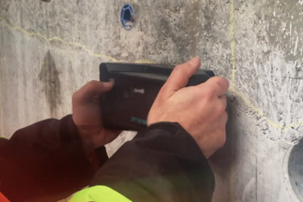
When a short-duration impact is applied on the surface of concrete, the applied disturbance (stress) propagates through the member. The wave propagation happens through propagation of three main types of waves: primary (compression) waves or P-waves, secondary (shear) waves or S-waves, and Rayleigh (surface) waves or R-waves. While P- and S- waves travel into the concrete along expanding spherical wave fronts, R-waves travel away from the impact point along the “near-surface”. As P- and S- waves propagate within concrete element, they get reflected by internal flaws or external boundaries. The impact-echo testing is commonly looking into reflection of P-wave, since the P-waves causes much larger displacement when compared to displacement due to other waves forms (e.g. S-waves).

Propagation of stress waves within concrete material

How to Determine P-Wave Velocity? 

The P-wave velocity (VP) can be determined with a short-duration mechanical impact at a particular distance (150 mm with a 5 mm diameter impactor) from two transducers linearly positioned at a known distance apart (~300 mm) along the surface of concrete. The P-wave speed can be then calculated via dividing the distance between the two transducers by the relative arrival times of the generate P-waves.

Schematic representation of the test setup to measure P-wave velocity

How Does Impact Echo Work?

The concept of the Impact-Echo test is illustrated in the Figure blow. An Impact-Echo test system is mainly composed of three main components: an impactor, a transducer, and a data logging system. The impact source is a small steel ball of different sizes capable of producing varying short-duration impacts. To conduct a test, an impulse is applied by the impactor at one-single point on the surface of concrete element. The resulting stress waves (P-wave, S-wave, and R-wave) propagate into the concrete medium in all directions; and travel back and forth between the test location and all existing boundaries and interfaces. The arrival of these echos on the surface of concrete element induces displacement.

Because of the high propagation speed and amplitude of P-waves, surface displacement caused by the arrival of reflected waves is dominated by the displacements caused by P-wave arrivals. The subsequent displacement associated with P-waves is measured using a sensitive transducer located near the impact point. The transducer converts the measured displacement into an analog signal of amplitude vs. time, called “waveform”. The waveform is recorded by a data logging system, which then proceeded for data analysis in either time-domain or frequency-domain.

Schematic representation of the impact echo to locate flaw/defect in concrete

Time-Domain vs Frequency Domain

Frequency domain analysis of the amplitude-time waveform

The frequencies associated with the peaks in the resulting amplitude spectrum are attributed to the dominant frequencies in the waveform, which are used to calculate the thickness of concrete component and/or the internal defects (e.g., crack, void, delamination, etc.). With knowing the P-wave velocity (VP) within concrete element, and the peak frequency (f) in Hz, the distance (T) to the reflecting interface (concrete back side and/or flaw) can be calculated:

where β is a shape (form) factor ranging from 0.84 to 0.96. The shape factor represents the volume in which the P-wave propagates, depending on the geometry of the structure.

Applications of Impact Echo Method

Impact-Echo is a very practical testing solution with a wide range of applications in condition assessment of concrete structures. The test can be used to:

1. Estimate Thickness of Concrete Elements

Impact Echo is widely used by engineers to assess the thickness of concrete elements. This is specially important in concrete elements with one-side access (Single Side Access), such as:

  • Tunnel linings: Thickness measurement is critical in the QC process for tunnel linings. It is also an important parameter for structural evaluation purpose.
  • Trunk Sewers: In trunk sewers, IE can help engineers estimate the thickness of existing lining. This becomes extremely challenging because intrusive methods involving hot work with core drilling is not a safe nor cost-effective solution. Moreover, there is always the risk of coring in shallow sections with high hydro static pressure.
  • Concrete Tanks: Testing concrete tanks that are used in industrial chemical processes is often challenging. Maintenance managers of such facilities often have very short downtime windows, and permission to get inside the tank is not always practical (unless during essential maintenance cycles). IE enables thickness measurement and quality assessment from exterior face.


Application of impact echo for estimating tickness of retaining walls

2. Locate Sub-Surface Defects

IE can be used to assess certain defects in concrete elements. IE can pinpoint the following defects:

  • Delamination: IE method can be used for detection of subsurface progressive defects such as delamination due to corrosion of steel reinforcement in concrete bridge decks, parking garage slabs, and concrete tanks.
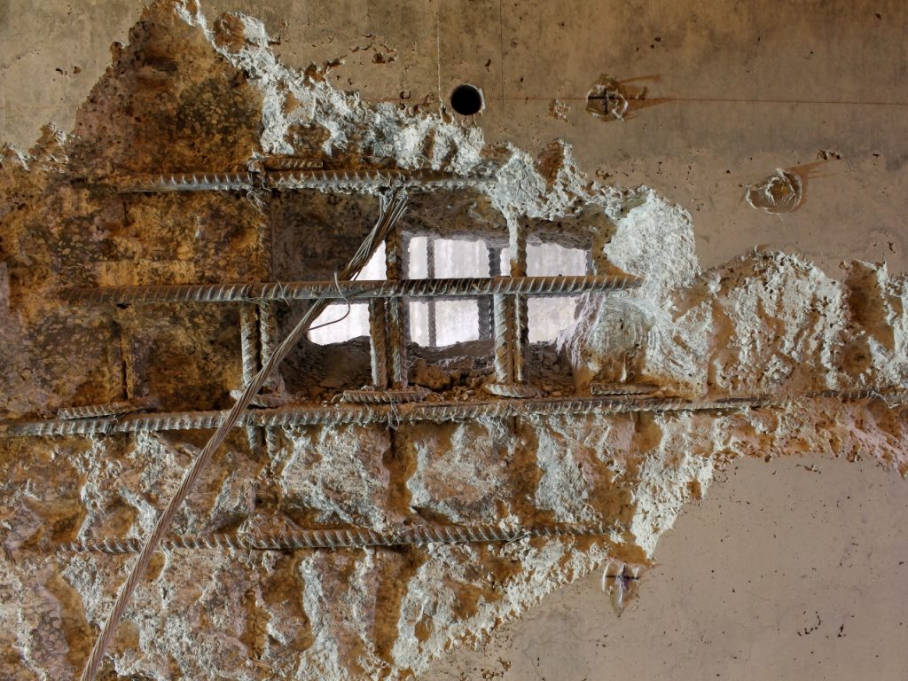
  • Honeycombing: IE is a great tool in the Quality Control and Quality Assurance of new construction. IE can be used to localize honeycombs in concrete.
  • Flaws/Voids/Debonding: IE can be utilized in different structural members in order to determine the location and depth of internal flaws (e.g. flaws and voids) and debonding in plain, reinforced, and post-tensioned concrete structures, including:
    • plates (slabs, pavements, walls, decks),
    • layered plates (concrete with asphalt overlays),
    • columns and beams (round, square, rectangular and many I and T cross-sections), and
    • hollow cylinders (pipes, tunnels, mine shaft liners, tanks).

Detailed Bridge Condition Survey -

Delamination of concrete in a bridge deck

Honeycomb concrete - UPE Scan

Honeycomb area during construction

3. Estimate Crack Depth

IE method can also be utilized to estimate the depth (D) of, straight, inclined or curved, surface-opening cracks in concrete elements. In this case, the impact echo method works based on two tranducers. The generated P-waves by impactor travels along the shortest trajectory between impactor and transducer. Mathematical equations are then used to estimate the depth of the surface-opening crack.

Schematic representation of the impact echo test setup for crack depth estimation

where L1 is the distance between the horizontal impact point and the crack; L2 denotes the distance between the second sensor and the surface-opening crack; L3 represents the distance between the impact point and the first sensor; VP is the P-wave velocity; and Δt denotes the travel time for the P-wave from the start of the impact to its arrival to the sensor 2

Practical Considerations

Like all other NDT methods, IE comes with its practical challenges for certain field conditions. The following factors should be considered when Impact-Echo Method is for condition assessment of concrete members:

  • Impact Contact Time: The smaller is the diameter of steel ball, the shorter is the contact time, and therefore, the higher would be the frequency range. In general, high frequency range components are correlated to P-waves propagation at shallower depths. Hence, the steel balls of smaller diameters are more suitable to generate the frequency components required for concrete scanning at shallower depth.
  • Transducer Distance from Impact Point: The distance from the impact point to the transducer should be from 20% to 50% of the depth of the shallowest reflecting interface to be measured. If the receiver is placed too far from the impact point, the waveform will include the effect of the reflected S-wave in addition to the reflected P-wave.
  • Fresh Concrete Testing: There are a few concerns on the accuracy of Impact-Echo test results on the fresh concrete. However, the impact-echo method has been successfully used for existing structures.
  • Effect of Sourounding Environment: Special attention should be given to the surrounding environment. If the stiffness of bedrock or underlying slab is very close to those of the main concrete element, the accuracy of the method will be affected.
  • Concrete Deck with Asphalt Overlay Testing: The use of Impact-Echo method for detection of delamination in concrete decks with asphalt overlays is highly limited to low temperatures, when the stiffness of asphalt is significantly high.
  • Boundaries of Delaminated Areas: The detection of the boundaries of delaminated area requires using a finer test grid.
  • Rough Concrete Surface: The impact-echo testing cannot be conducted on open textured concrete such as gravel rough surface. In such cases, concrete surface under testing should be rubbed smooth with a grinder.
  • Overlaid Bridge Decks: Sub-surface mapping using the impact-echo technique is more complicated for overlaid bridge decks. The test method cannot assess the condition of the deck in areas where the overlay is debonded.
  • Boundary Effects: Geometrical and boundary effects, especially for structural elements like girders, piers, and pier caps, may affect the accuracy of the impact-echo testing results.