In this article, we will review an interesting category of ultrasonic test methods for concrete inspection and testing: Ultrasonic Pulse-Echo (UPE) is widely used for the inspection of concrete elements. The method has proven to be extremely useful in determining the thickness of concrete elements with one side access (i.e. tunnel linings, trunk sewer linings, abutment walls), detect sub-surface defects such as voids, honeycombing, and delamination, and to verify Location of grouting defects in tendon ducts.
Ultrasonic Pulse Echo
Ultrasonic Pulse Echo is a non-destructive testing (NDT) method for scanning sub-surface targets in concrete elements. UPE methods use acoustic stress waves to study the properties of sub-surface layers, and locate defects by identifying any anomaly of acoustical impedance that is different from concrete. The test method was developed to address practical limitations of the general Ultrasonic Pulse Velocity test, such as the need to access both sides of the concrete element.
The ACI 228.2R Section 3.2.2 provides a comprehensive review on the evolution of ultrasonic pulse echo method, and instruments over the past few decades. While traditional UPE instruments were capable of providing A-Scans and B-Scans, modern Ultrasonic Pulse Echo Tomography devices are capable of providing real-time B-Scans that would enable engineers to see sub-surface targets with further clarity. Mobile-based Applications, along with Artificial Intelligence and Modern signal processing techniques have brought superior speed and clarity, with ease of use.
Ultrasonic Pulse Echo for Evaluating Thickness of Concrete Walls
How Does Ultrasonic Pulse Echo Work?
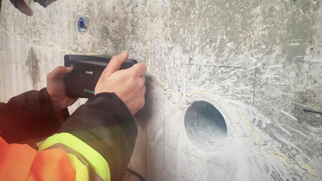
As we discussed earlier, UPE uses stress waves. The principle concept behind the test is measuring the transit time of ultrasonic wave in concrete. A modern UPE instrument consists of an array of piezoelectric transducers that are capable of exciting concrete surface through short-burst high amplitude pulse-high voltage and high current- (see Strategic Highway Research Program-SHPR2, TRB, 2013). As the pulse propagates within the concrete, it gets reflected and refracted at the interface of voids, or other internal targets. Any anomaly in acoustical impedance leads The emitted impulse and the reflected stress waves are monitored at the receiving transducer. The signals are analyzed to calculate the wave travel time.
According to the SHRP2, “Based on the transit time or velocity, this technique can also be used to indirectly detect the presence of internal flaws, such as cracking, voids, delamination or horizontal cracking, or other damages.”

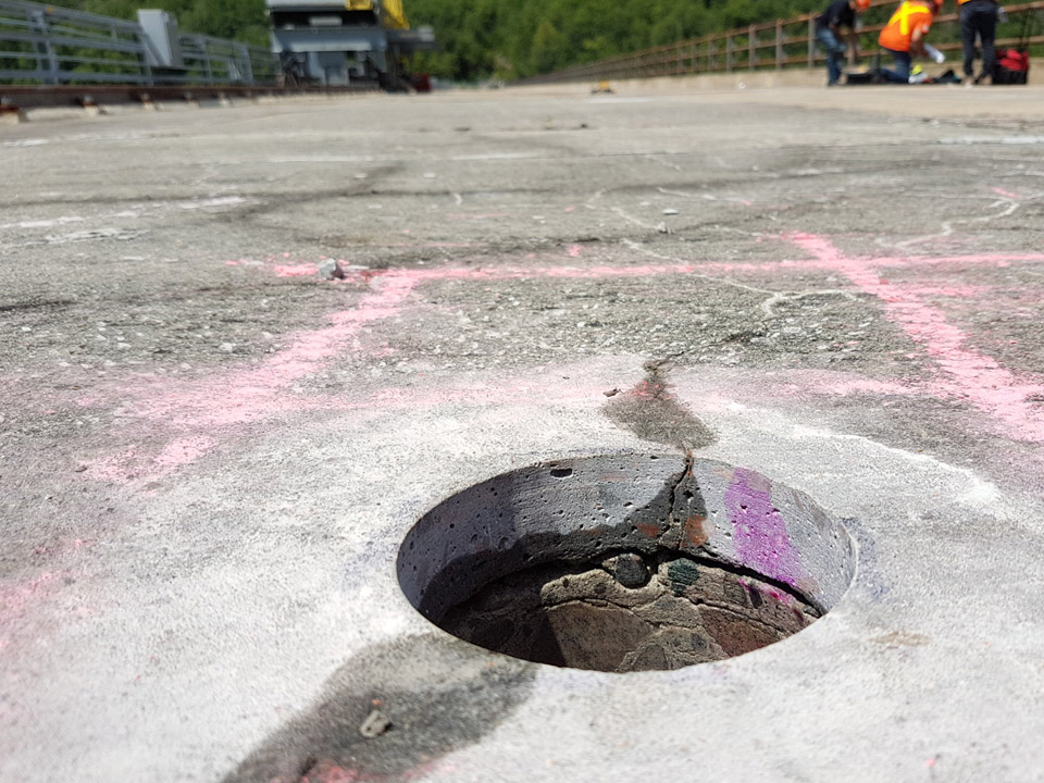
Ultrasonic Pulse Echo Tomography on Concrete Bridge Decks to locate delamination and voids
Applications of UPE Methods
Ultrasonic Pulse Echo methods are widely used in concrete inspection and testing. The following section describes the main applications and Use Cases:
1. Estimate Thickness of Concrete Elements
Ultrasonic Pulse Echo is widely used by engineers to assess the thickness of concrete elements. This is specially important in concrete elements with one-side access (Single Side Access), such as:
- Tunnel linings: Thickness measurement is critical in the QC process for tunnel linings. It is also an important parameter for structural evaluation purpose.
- Trunk Sewers: In trunk sewers, UPE can help engineers estimate the thickness of existing lining. This becomes extremely challenging because intrusive methods involving hot work with core drilling is not a safe nor cost-effective solution. Moreover, there is always the risk of coring in shallow sections with high hydro static pressure.
- Concrete Tanks: Testing concrete tanks that are used in industrial chemical processes is often challenging. Maintenance managers of such facilities often have very short downtime windows, and permission to get inside the tank is not always practical (unless during essential maintenance cycles). UPE enables thickness measurement and quality assessment from exterior face.

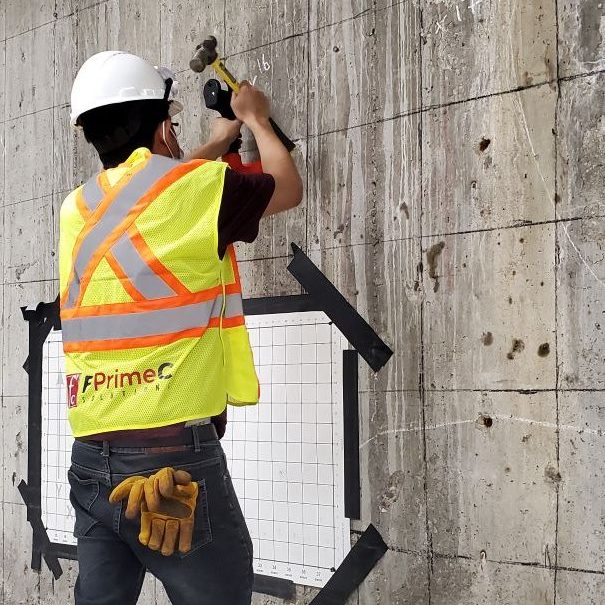
Ultrasonic Pulse Echo Testing in Concrete Tanks – Paper Mill, Gatineau, QC
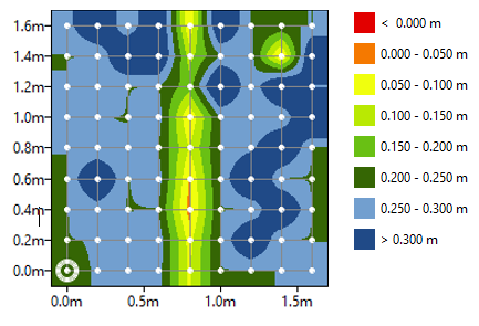
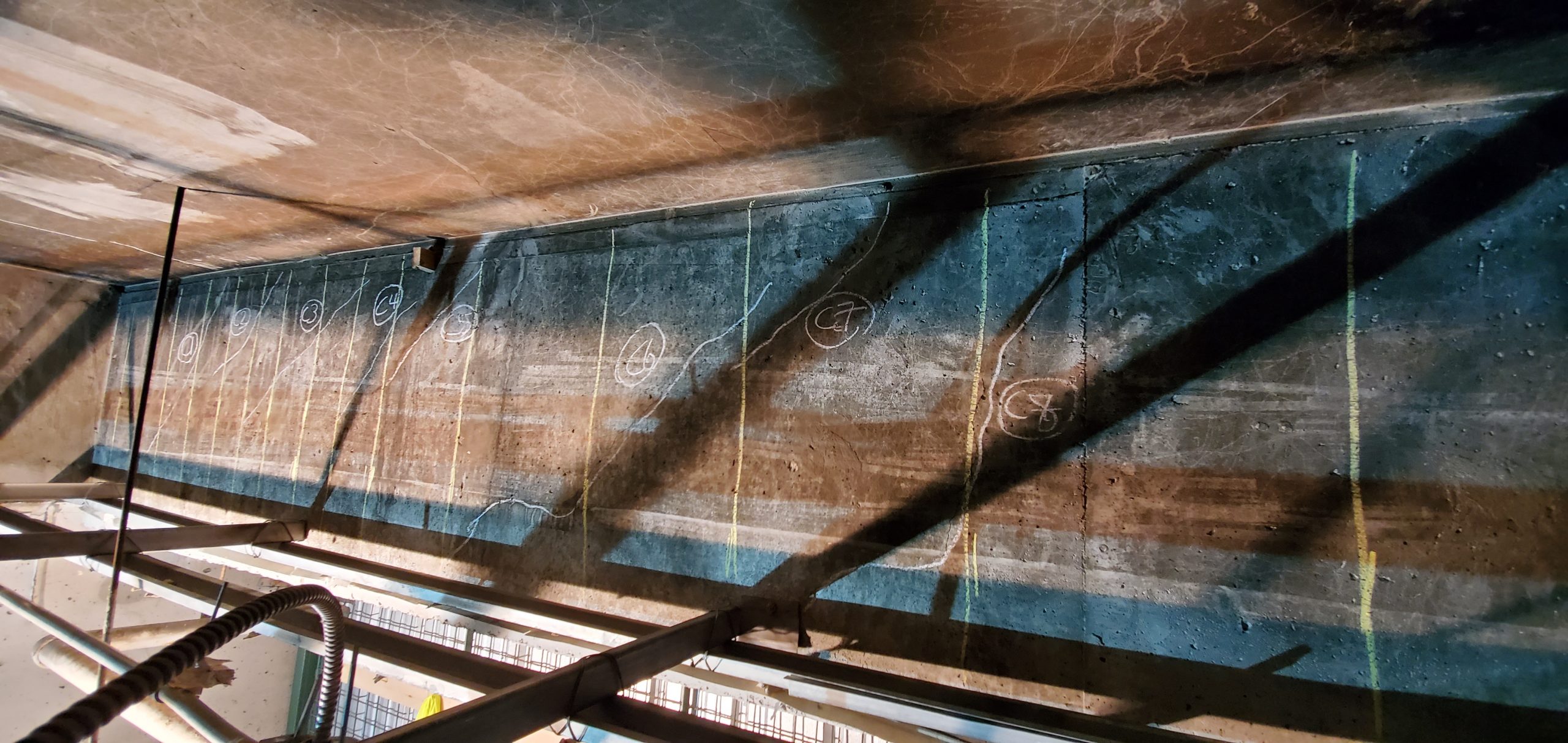
Example of UPE tomography maps and Thickness Measurements (Tests on a concrete slab in laboratory conition)
2. Grouting Defects in Tendon Ducts
Along with Ground Penetrating Radar (GPR) and Impact-Echo, UPE can provide critical information about voids and defects that might have happened during grouting process of tendon ducts in post-tensioned concrete elements.
3. Locate Sub-Surface Defects
UPE tomography can be used to assess certain defects in concrete elements. UPE can pinpoint the following defects:
- Delamination: UPE methods can be used to assess the location and extent of delamination in concrete bridge decks, parking garage slabs, and concrete tanks
- Honeycombing: UPE is a great tool in the Quality Control and Quality Assurance of new construction. UPE can be used to localize honeycombs in concrete.
Delamination of concrete in bridge decks
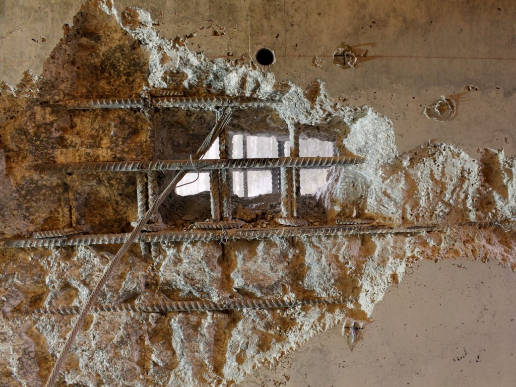
Honeycomb area during construction
4. Quality Control and Quality Assurance
UPE can used as in-direct method to assess the overall quality of concrete. Through the measurement of pulse velocity, engineers can evaluate the quality of concrete materials after construction.
5. Evaluation of Fiber Reinforced Concrete
While GPR has certain pratical limitations in evaluation Fiber Reinforced Concrete (FRC) elements, UPE methods provide a reliable alternative in thickness measurement and quality control of elements. This makes them an interesting alternative in inspection and testing of concrete linings in tunnels.
Limitations of UPE and Practical Considerations
Like all other NDT methods, UPE comes with its practical challenges for certain field conditions.
- Close Spacing of Test Points: In order to generate reliable and precise maps of sub-surface defects, engineers need to use close spacing between test points. This can make the test time-consuming for large test areas. A practical solution is to use another method such as GPR for rapid screening, and use UPE for high-resolution imaging of defects.
- Coupling Issues: The quality of acoustic signals depend heavily on the coupling of the transducer and concrete surface. This cab be quite challenging for rough surfaces. Modern devices have tried to address the issue with spring supported mechanism at the base of transducers to allow for maneuvering around the rough areas.
- Undetected Defects: Certain defects might remain undetected. This is specially true for very shallow flaws or when operators work with low frequencies.


Mohammed Aqel
What is the maximum applicable thickness of concrete elements?
Non-destructive Evaluation of Concrete in Mine Facilities - FPrimeC Solutions Inc.
[…] Ultrasonic Pulse Echo Tomography can be used to assess the following key parameters: […]